We called it Triangle Visibility Buffer because this rendering technique is keeping track of triangles through the whole rendering pipeline and stores visibility of every opaque triangle in the scene in a buffer. The technique is very suitable for target hardware platforms that have only limited amounts of high-speed memory to store render data but need to support large resolutions. It is also most suitable for rendering on high-resolution displays with 4k, 5k, or 8k resolutions.
You can find the source code accompanying this blog entry at
In this repository, there are PC DirectX 12 / Vulkan, Linux Vulkan and macOS / Metal 2 implementations available. On request, there is also source code for various console platforms available. The following text will only refer to the DirectX 12 implementations for consistency. Finding the Vulkan and macOS counterparts in the code base is left to the reader.
Following the data flow in the Triangle Visibility Buffer rendering pipeline, the first stage is the triangle removal stage, which culls invisible triangles from the data set.
Multi-View Triangle Cluster Culling / Triangle Filtering
The number of polygons increases every year in games. Hardware can become bottlenecked in the Command Processor, in case empty draw calls are spawned, in the vertex shader with the number of vertices to transform, with backface culling and clipping and or in the rasterizer because small triangles that are not visible make it primitive bound.
To reduce the number of triangles that are going into the graphics pipeline in general, a triangle removal stage is added as a first step to the whole rendering system. This way the graphics pipeline can be better utilized with the visible triangles.
Triangle removal is not a new concept and was utilized on certain platforms already a decade ago or probably even longer. Due to the triangle complexity of modern games, it was revived in recent years in talks by [Chajdas][Wihlidal] because modern hardware seems to benefit from it.
The techniques used in the demo to remove triangles consist of the following consecutive stages:
- Cluster culling: cull groups of 256 triangles with a similar orientation on the CPU
- Triangle filtering: cull individual triangles in an async compute shader individually
- Draw call compaction: remove empty draw calls with no triangles left and order the remaining draw calls sequentially in a compute shader
The demo implementation does all the above for the main camera view and the shadow map view at the same time. We call this Multi-View Triangle removal.
Triangle Cluster Culling on the CPU
Triangle cluster culling -running in this case on the CPU- removes invisible chunks of 256 triangles with similar orientation. This is done by picking the first 256 triangles of a mesh and then testing them against a visibility test cone. In the following Image 1, the triangles and the face normals of those triangles are represented by the orange lines.
 Image 1 - Triangle Cluster Culling - The Test Cone
The light blue triangle is the test cone. In case the eye or the camera is inside this test cone, the triangles are considered not visible. To find the center of the cone, we start out by accumulating the face normals of the triangle cluster negatively as shown in Image 2.
 Image 2 - Triangle Cluster Culling - Negatively accumulating Triangles to find the cone center
To calculate the cone open angle, the most restrictive triangle planes are taken from the triangle cluster as shown in Image 3.
 Image 3 - Triangle Cluster Culling - Calculating the Test Cone Planes
If the camera or eye is in the area of the test cone, the triangle cluster is not visible and can, therefore, be removed.
The effectivity of this simple cluster culling mechanism depends on the scene data. In case there are a lot of triangles that face in a similar direction, it will be more efficient, in case triangles are facing in different directions, it is lower.
The test scene -San Miguel- in the Visibility Buffer demo doesn’t have many clusters of triangles that are facing in a similar direction and therefore triangle cluster culling is not very efficient. This might be different with geometry that is tessellated by hardware. By default, triangle cluster culling is due to poor efficiency switched off in the demo.
The code for cluster culling can be found in Visibility_Buffer.cpp, and therein triangleFilteringPass() and then cullCluster().
Triangle Filtering on the GPU
To remove invisible triangles, an async compute shader is executed on each triangle. It runs 256 triangles in one batch and tests if triangles are
- Degenerate
- Back-facing
- Clip through the near clipping plane of the view frustum
- Clip through or are outside of the view frustum
- Are too small to cover a pixel center or sampling point
Triangles that pass all tests will be appended to an index buffer. This index buffer is then called a filtered index buffer.
All the source code for this section can be found in the shader triangle_filtering.comp.fsl and in there in the function FilterTriangle().
Degenerate and Back-facing Triangles
Triangles that face away from the viewer are not visible and therefore need to be culled. This implementation uses a technique described by [Olano]. He calculates the determinant of the 3x3 clip-space matrix consisting of the three vertices of the triangle. In case the determinant is larger than 0, it has no inverse and therefore is back-facing and can be culled.
If the determinant is 0, the triangle is degenerate, or is being viewed edge-on and has zero screen-space area. Degenerate triangles might be introduced in hardware tessellation or in case there is a bug in the art asset pipeline.
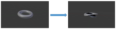 Image 3 - Backface Culling
#if ENABLE_CULL_BACKFACE
 // Culling in homogenous coordinates
 // Read: "Triangle Scan Conversion using 2D Homogeneous Coordinates"
 //       by Marc Olano, Trey Greer
 //       http://www.cs.unc.edu/~olano/papers/2dh-tri/2dh-tri.pdf
 float3x3 m = float3x3(vertices[0].xyw, vertices[1].xyw, vertices[2].xyw);
 if (cullBackFace)
   cull = cull || (determinant(m) >= 0);
#endif
Back-face culling can potentially remove 50% of the geometry.
Near Plane Clipping
Triangles that are in front of the near clipping plane of the view frustum need to be culled. To check, if the triangle is in front of the near clipping plane, the following code checks if the w component of each vertex is below zero. In case this is true, it flips the w component, to make sure it is not projected on two sides of the screen.
for (uint i = 0; i < 3; i++)
{
if (vertices[i].w < 0)
{
++verticesInFrontOfNearPlane;
// Flip the w so that any triangle that straddles the plane
// won't be projected onto two sides of the screen
vertices[i].w *= (-1.0);
}
…
}
If all three vertices of the triangle are in front of the near clipping plane, the triangle gets culled:
if (verticesInFrontOfNearPlane == 3)
return true;
Frustum Culling
Triangles whose vertices are all on the negative side of the clip-space cube are outside the view frustum and therefore can be culled.
The following image 4 shows the camera situated close to a table in the San Miguel scene and the remaining triangles after frustum culling.
 Image 4 - Triangle Frustum Culling
...
vertices[i].xy /= vertices[i].w * 2;
vertices[i].xy += float2(0.5, 0.5);
…
If any vertices of a triangle are outside of this 0 .. 1 range, it will be culled.
...
float minx = min(min(vertices[0].x, vertices[1].x), vertices[2].x);
float miny = min(min(vertices[0].y, vertices[1].y), vertices[2].y);
float maxx = max(max(vertices[0].x, vertices[1].x), vertices[2].x);
float maxy = max(max(vertices[0].y, vertices[1].y), vertices[2].y);
if ((maxx < 0) || (maxy < 0) || (minx > 1) || (miny > 1))
return true;
...
Small Primitive Culling
Triangles are considered too small, in case they do not overlap with a pixel center or a sample point after projection.
The following image shows very small triangles in-between sampling points:
 Image 5 - Small Primitive Culling
Although the triangles in image 5 are too small to be visible, the rasterizer might still spend cycles dealing with them. In case the GPU can only deal with one primitive per cycle per tile, the cost of even one invisible triangle can become high.
This is why small triangles need to be removed before they hit the graphics pipeline.
The following code for the small triangle test generates a bounding box in screen-space around a triangle, then uses the x and y value of this bounding box to see if it overlaps a pixel center or sampling point in the case of MSAA.
// Scale based on distance from center to msaa sample point
int2 screenSpacePosition = int2(screenSpacePositionFP * (SUBPIXEL_SAMPLES * samples));
minBB = min(screenSpacePosition, minBB);
maxBB = max(screenSpacePosition, maxBB);
if (any(((minBB & SUBPIXEL_MASK) > SUBPIXEL_SAMPLE_CENTER) &&
((maxBB - ((minBB & ~SUBPIXEL_MASK) + SUBPIXEL_SAMPLE_CENTER)) <
(SUBPIXEL_SAMPLE_SIZE))))
{
return true;
}
Multi-View Triangle Removal
Triangle removal comes at the cost of loading for every triangle the index and vertex data, transform vertices, and then, later on, append the triangle data to the filtered index buffer. It appears that the cost of accessing the triangle data seems to be higher than the cost of running the visibility tests.
As long as the numbers of triangles in the scene are high, this cost should be offset by the gains on modern GPUs.
One way to amortize this cost, even more, is to remove invisible triangles for several views -like a main camera view, a shadow map view, reflective shadow map view, etc.- at the same time.
That means if a triangle is visible in the main camera view but not in the shadow map view, it is considered visible in both views. In other words, the remaining set of visible triangles will be the least common denominator between all views; reducing the effectiveness of triangle removal.
Although the overall number of triangles that are removed with a multi-view triangle removal stage is smaller compared to just removing triangles for each view separately, huge performance gains are achieved by just loading the triangle data only once in that case.
Here is the source code in triangle_filtering.comp.fsl that executes FilterTriangle() for several views:
for (uint i = 0; i < NUM_CULLING_VIEWPORTS; ++i)
{
float4x4 worldViewProjection = uniforms.transform[i].mvp;
float4 vertices[3] =
{
mul(worldViewProjection, vert[0]),
mul(worldViewProjection, vert[1]),
mul(worldViewProjection, vert[2])
};
CullingViewPort viewport = uniforms.cullingViewports[i];
cull[i] = FilterTriangle(indices, vertices, !twoSided,
viewport.windowSize, viewport.sampleCount);
if (!cull[i])
InterlockedAdd(workGroupIndexCount[i], 3, threadOutputSlot[i]);
}
Multi-View Triangle Removal - Results
The San Miguel scene used in the demo has around 8 million triangles. When the demo starts up in the default camera view - shown in image 6-, after multi-view triangle removal, the filtered index buffer for the shadow map view indexes 1.843 million triangles, while the filtered index buffer for the main view indexes 2.321 million triangles.
 Image 6 - Default start-up view of the Visibility Buffer demo
Triangle removal as described here or similar approaches are now used by every major developer in next-gen rendering systems and future graphics API design is picking up this idea and might improve geometry handling more.
Draw Call Compaction
The async compute shader for Triangle Filtering runs on batches of 256 triangles as described above. This stage removes all non-visible triangles by appending only visible triangles to the “filtered index buffer”.
This might lead to a situation where the removal of triangles ends up creating an empty draw call:
- Batch0 - start index: 0 | num of indices: 12
- Batch1 - start index: 12 | num of indices: 256
- Batch2 - start index: 268 | num of indices: 120
- Batch3 - start index: 388 | num of indices: 0 (empty batch)
In this list, Batch3 ends up being empty.These "holes" impact performance since the GPU command processor has to do all the work setting up data for that draw call, which is wasted work if it is empty.
This shader removes empty draw calls and aligns the remaining ones so that the ExecuteIndirect call is efficient.
Image 7 shows the flow from triangles that are removed with culling tests to draw calls that need to be compacted.
 Image 7 - Draw Call Compaction
The batch compaction compute shader checks if the draw call is empty and then removes those calls by filling a new draw argument buffer with only usable draw call data. This new draw argument buffer is later used by ExecuteIndirect. This same shader also fills a per draw indirect material buffer which holds the material index for each draw call. It also determines the overall number of draw calls that will be passed as the final draw counter to the ExecuteIndirect call.
On a high-level view, the Triangle Visibility Buffer rendering system went through the following stages so far:
- [CPU] Early discard geometry not visible from any view using cluster culling
- [CS] Generate N index and N ExecuteIndirect buffers by culling and filtering triangles against the N views (one triangle per compute shader thread)
- [CS] Draw call compaction
- For each, i view use ith index buffer and ith indirect argument buffer
With all the draw data optimized for usage, the next stage is filling the actual Visibility Buffer with ExecuteIndirect.
Filling the Visibility Buffer - ExecuteIndirect
The Triangle Visibility Buffer will hold indices into triangle data in an 8:8:8:8 render target similar to [Burns][Schied]. The index consists of a packed 32-bit value:
- 1-bit Alpha-Masked
In the demo, one bit holds information on if the geometry requires alpha masking or not. The PC requires a dedicated code path for each with its own ExecuteIndirect.
- 8-bit drawID - indirect draw call id
An 8-bit value represents the id of the draw call to which the triangle belongs. In this implementation, there is space for 256 draw calls
- 23-bit triangleID
A 23-bit value holds an id that describes the offset of a triangle inside a draw call. In other words, it is relative to the drawID.
The render target holding this data is filled with ExecuteIndirect calls in parallel with the Depth Buffer.
All ExecuteIndirect calls read vertex buffers, index buffers, and a material buffer, that is used to apply various materials.
There are four different vertex buffers:
- Position
- Texture coordinates
- Normals
- Tangents
Separating vertex data into four buffers (also called non-interleaved vertex data) turned out to be more efficient due to position and texture coordinates being used more often than normals and tangents.
Looking at the separate stages: - Triangle filtering uses
- Filling the Visibility Buffer uses
- Position
- Texture coordinates for alpha testing
- Shading uses
- Position
- Texture coordinates
- Normals
- Tangents
The ExecuteIndirect calls also expect index buffers that are used to index into the vertex buffers. This demo is using six “filtered” index buffers that were generated during triangle removal by appending only visible triangles to them. There are two sets for the camera view and the shadow map view of three index buffers for triple buffering the swap chain. The triple buffer was necessary for the async compute shader used in triangle removal.
The ExecuteIndirect calls also expect “filtered” indirect argument buffers that were generated during the draw call compaction stage after triangle removal.
The last buffer fed to the ExecuteIndirect calls is the texture id or material buffer (also generated during draw call compaction), which is used to represent a wide range of materials in the scene.
All the source code can be found in Visibility_Buffer.cpp and there in drawVisibilityBufferPass() and in visibilitybuffer_pass.frag.fsl.
In the San Miguel test scene, the number of indirect draw calls in each of the four ExecuteIndirect calls are:
- Shadow opaque: 163
- Shadow alpha masked: 50
- Main view opaque: 152
- Main view alpha masked: 50
As soon as these four ExecuteIndirect calls have finished, the Visibility Buffer and the Depth buffer are filled with one layer of triangles and one layer of pixels. In other words overdraw of triangles and pixels is removed for opaque geometry.
The demo holds implementations for the described Visibility Buffer approach and a G-Buffer based Deferred Shading approach. The way the G-Buffer is filled resembles the way the Visibility Buffer is filled. The main difference is the memory usage patterns.
Memory Usage - Visibility Buffer vs. G-Buffer
Memory bandwidth is one of the more limiting factors for the performance of games, especially on lower-end platforms or on platforms that need to support 4k and higher resolutions.
The increasing size of G-Buffers during the last 10 years makes the commonly used Deferred Shading techniques more bandwidth-hungry.
Games use vertex and index buffers, other data like textures, draw arguments, uniforms, descriptors, and then render targets. Render targets scale with screen size and for larger screen resolutions represent a very large part of the memory occupied during rendering.
One of the advantages of the Visibility Buffer is that it fits into two 32-bit render targets (Triangle Visibility in 32-bit and depth visibility in 32-bit as well). The following text will compare the memory usage of the demo implementation of the Visibility Buffer and the G-Buffer implementation.
The usage of vertex and index buffers to feed the ExecuteIndirect calls are the same in the Visibility Buffer and the G-Buffer implementation as shown in Image 8:
 Image 8 - Memory usage of the Vertex and Index Buffers
Additionally, there is data used for textures (roughly 21 MB), draw arguments, uniforms, descriptors etc. (roughly 2 MB). From a memory perspective, the most interesting memory is the one that is used for screen-space render targets. Image 9 shows the render target memory occupied with a resolution of 1080p and various MSAA settings for the Visibility buffer:
 Image 9 - Visibility Buffer Memory at 1080p
Image 10 shows the render target memory occupied in a resolution of 1080p and various MSAA settings for a G-Buffer:
 Image 10 - G-Buffer Memory at 1080p
Comparing the 1080p memory numbers, the G-Buffer with 2x and 4x MSAA more than doubles in size as expected from going from two 32-bit render targets to five.
With a monitor or TV supporting 4k (3840x2160) the delta between the G-Buffer compared to the Visibility Buffer becomes bigger as shown in Image 11 and 12:
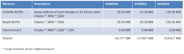 Image 11 - Visibility Buffer Render Target memory at 4k
 Image 12 - G-Buffer Render Target memory at 4k
The numbers provided are only estimates on PC because the driver and the way memory is fragmented might change how much one render target actually occupies.
These numbers show how filling and reading a G-Buffer with large screen resolutions for Deferred Shading can become a memory bandwidth bottleneck, depending on the memory bandwidth of the used GPU. This becomes even more dramatic with 5k and 8k displays.
In other words: one motivation to implement a Visibility Buffer-like approach is to reduce memory bandwidth on high-res displays on platforms that do not have much high-speed memory, like hardware-tiled platforms or some console platforms.
Shading
After the Visibility Buffer is filled with one layer of triangles for the opaque pass, and the depth buffer is filled with one layer of pixels, the scene can be shaded. To prepare for shading the scene, a list of lights per screen-space tile is generated upfront (Tiled Light List).
Tiled Light List
To deal with a large number of lights, the demo implementation splits the screen-space into tiles and identifies lights that need to be rendered in those tiles. In the actual shading pass, this light list will be used to do one screen-space lighting pass for all light sources for opaque and transparent objects.
To generate this list, a compute shader runs on 64 lights per tile. It compares the bounding volume of the light with its x and y-direction to the x and y-direction of the tile in screen-space, in case it is in the tile, it adds the light to the light cluster and increases the light count for that cluster. There is also an early out for lights that are behind the camera.
The source code for generating the list of lights in those tiles can be found at cluster_lights.comp.fsl.
Forward++
Because the lighting technique uses the Visibility Buffer with its one layer of optimized triangle data in one screen-space pass, we call it Forward++ compared to Forward+ that would use several draw calls.  Image 13 - Shading the Visibility Buffer with Forward++
On a high level, the shading algorithm goes through the following steps:
- Get drawID/triangleID at screen-space pixel position
- Load data for the 3 vertices from the IB and then the VB
- Compute the partial derivatives of the barycentric coordinates – triangle gradients
- Interpolate vertex attributes at pixel position using gradients
- Calculate Directional light contribution (in the demo either Blinn-Phong or PBR)
- Add point light contributions by going through the tiles of the tiled light list
The source code for applying the lights is in visibilityBuffer_shade.frag.fsl.
To calculate the partial derivatives, we are using the following equation from [Schied] in Appendix A Equation (4):  Equation 1 - Partial Derivatives
The implementation of this equation looks like this:
// Computes the partial derivatives of a triangle from the projected
// screen space vertices
DerivativesOutput computePartialDerivatives(float2 v[3])
{
DerivativesOutput output;
float d = 1.0 / determinant(float2x2(v[2] - v[1], v[0] - v[1]));
output.db_dx = float3(v[1].y - v[2].y, v[2].y - v[0].y, v[0].y - v[1].y) * d;
output.db_dy = float3(v[2].x - v[1].x, v[0].x - v[2].x, v[1].x - v[0].x) * d;
return output;
}
The partial derivatives in this code are calculated without intrinsics to preserve as much precision as possible.
The actual shading code is rather straightforward. The directional light is applied first and the point lights are applied later in a for loop depending on their visibility in the screen tiles:
…
// directional light
shadedColor = calculateIllumination(normal, uniforms.camPos.xyz, uniforms.esmControl,
uniforms.lightDir.xyz, isTwoSided, posLS, position, shadowMap,
diffuseColor.xyz, specularData.xyz, depthSampler);
// point lights
// Find the light cluster for the current pixel
uint2 clusterCoords = uint2(floor((input.screenPos * 0.5 + 0.5) *
float2(LIGHT_CLUSTER_WIDTH, LIGHT_CLUSTER_HEIGHT)));
uint numLightsInCluster = lightClustersCount.Load(LIGHT_CLUSTER_COUNT_POS(clusterCoords.x,
clusterCoords.y) * 4);
// Accumulate light contributions
for (uint i = 0; i < numLightsInCluster; i++)
{
uint lightId = lightClusters.Load(LIGHT_CLUSTER_DATA_POS(i, clusterCoords.x,
clusterCoords.y) * 4);
shadedColor += pointLightShade(lights[lightId].position, lights[lightId].color,
uniforms.camPos.xyz, position, normal,
specularData, isTwoSided);
}
This code and the setup might likely change in future iterations of the demo. Any Ray Tracing code might benefit from the existence of partial derivatives and the fact that the visibility of triangles is optimized in the Visibility Buffer.
Visibility Buffer - Benefits
Comparing the Visibility Buffer to a Deferred Shading system with a large G-Buffer shows the following benefits.
Memory Bandwidth
Due to the smaller render target memory footprint, the Visibility Buffer offers memory bandwidth benefits compared to a G-Buffer. This becomes eminent in scenarios where the screen resolution is high or where the amount of fast memory is so limited that only two 32-bit render targets or even a tiled region of render targets fit.
Memory Access Patterns
When shading happens, triangle data is fetched from the filtered index buffer in the Visibility Buffer. The actual fetch of data from the index/vertex buffers happens similar to a regular draw call but continuously in screen-space once. In other words, the memory access of index and vertex buffers apart from the indirection through the Visibility Buffer is the “optimal” access pattern that the architects of GPUs had in mind. Compared to a regular forward renderer this only happens once for opaque objects in screen-space and not for several draw calls.
We see highly coherent cache hit rates of 99% L2 cache hits for textures, vertex, and index buffers. Therefore lighting the triangles appears to be fast.
To apply a light in a G-Buffer, a larger memory area has to be accessed due to the more redundant nature of screen-space data.
These two benefits are underlined by the performance measurements shown below.
Material Variety
The Visibility Buffer can represent a much wider range of materials due to the fact that material parameters do not have to be stored per-pixel in a G-Buffer. All the lessons learned from using materials in forward renderers need to be extended by the idea that the Visibility Buffer uses bindless texture arrays, other than that it should be the same.
Miscellaneous
There are several questions that usually come up in discussions about the Triangle Visibility Buffer implementation.
Why didn’t we implement this earlier?
What is described here was not a straightforward process of implementing one paper. We started out with [Schied] in September 2015. Christoph Schied came to our office and implemented his approach in our old rendering framework at that point in time in OpenGL. We then simplified everything over the following 2 ½ years to a point our approach transformed into the approach taken by [Burns]. Compared to [Burns], the actual storage of triangles in the Visibility Buffer happens due to the triangle removal and draw compaction step with an optimal “massaged” workload set, with ExecuteIndirect reducing CPU overhead. Because this requires a compute shader, it was not possible at the time.
After the Visibility Buffer is filled with one layer of triangles and the depth buffer holds one layer of pixels, the now one-time screen-space shading can be executed faster compared to Deferred Shading and a Forward Renderer due to better memory access patterns.
[Burns] couldn't use compute shaders and therefore a tiled light list was not possible.
How often do you have to skin animated objects?
There are three stages that transform vertices for triangle removal, filling the Visibility Buffer and then shading. After the triangle removal stage, the transformation has -hopefully- only to happen on less than half of the triangles compared to triangle removal.
To reduce the number of times that a triangle has to be transformed, in a future iteration of the demo application, pre-transformation of triangles will be implemented.
How about Deferred Decals?
If you still use a Decal system it might be time to switch to an async compute-driven texture synthesis system. Other than that the equivalent of Deferred Decals can be implemented after the Visibility Buffer fill, fetching triangle and normal data from the Visibility Buffer and applying the end result in the back-buffer similarly to a Deferred Decal system.
Performance Numbers
Over the years, we collected performance numbers on various platforms ranging from console platforms to macOS and now PC with DirectX 12 and Vulkan. The Visibility Buffer demo allows switching between a Deferred Shading implementation with a G-Buffer that resembles what is used in games and the actual Visibility Buffer implementation.
Both are similar when it comes to how the data is set up to be rendered into the Visibility Buffer / Buffer. So both use the ExecuteIndirect setup described above on all platforms. The main difference is the usage of the G-Buffer.
Below are performance numbers for the DirectX 12 implementation running at 4k from an older version of the codebase.  Image 14 - Visibility Buffer Performance Numbers

Image 15 - Deferred Shading Performance Numbers
The column that is named “Culling” shows the performance cost of triangle culling and filtering. Most of the other columns are self-explanatory.
With increasing screen resolution, the difference in performance between a G-Buffer and the Visibility Buffer becomes apparent. The difference translates also to console platforms in 1080p and 4k resolutions.
Future
For future iterations of the Visibility Buffer, we are looking at Physically Based Materials, Ray Tracing and Object-Space Shading. In case we find any noteworthy results, they will be shared in another blog post.
Credits
Like all the work at our company, a research project like this for such a long time is touched by a large number of people. In no particular order, there was Leroy Sikkes, Jesus Gumbau, Thomas Zeng, Max Oomen, Jordan Logan, Marijn Tamis, David Srour, Manas Kulkarni, Volkan Ilbeyli, Andreas Valencia Telez, Eloy Ribera, Antoine Micaelian who worked at one point or another on this project. In case I forgot someone, I will add the person … let me know :-)
Update: it is the year 2021: this list can be extended by about 30 more people. Everyone who ever worked at our company worked on this in one or two ways since 2015 ... we also need to thank more companies to support this research: Apple, AMD, INTEL, Google, and I am forgetting probably a few, they span off projects with us over the years. Thanks for all the support!
We are using GeometryFX and the Vulkan Memory Manager from AMD and many other open-source libraries. We want to thank all the open-source contributors for sharing their code and knowledge. Without these contributions writing your own game engine with a framework like the Forge wouldn’t be as easily possible. We are hoping that this spirit lives on and others are encouraged to do the same.
References
[Burns] Christopher A. Burns, Warren A. Hunt “The Visibility Buffer: A Cache-Friendly Approach to Deferred Shading” Journal of Computer Graphics Techniques (JCGT) 2:2 (2013), 55- 69. Available online at http://jcgt.org/published/0002/02/04
[Chajdas] Matthaeus Chajdas “GeometryFX” http://gpuopen.com/gaming-product/geometryfx/
[Engel2009] Wolfgang Engel, “Light Pre-Pass”, “Advances in Real-Time Rendering in 3D Graphics and Games”, SIGGRAPH 2009, http://halo.bungie.net/news/content.aspx?link=Siggraph_09
[Lagarde] Sebastien Lagarde, Charles de Rousiers, “Moving Frostbite to Physically Based Rendering”, Course notes SIGGRAPH 2014
[Olano] Marc Olano, Trey Greer, “Triangle Scan Conversion using 2D Homogeneous Coordinates”, https://www.csee.umbc.edu/~olano/papers/2dh-tri/
[Schied2015] Christoph Schied, Carsten Dachsbacher “Deferred Attribute Interpolation for Memory-Efficient Deferred Shading”, http://cg.ivd.kit.edu/publications/2015/dais/DAIS.pdf
[Schied2016] Christoph Schied, Carten Dachsbacher “Deferred Attribute Interpolation Shading”, GPU Pro 7, CRC Press
[Wihlidal] Graham Wihlidal, “Optimizing the Graphics Pipeline with Compute”, GDC 2016, http://www.frostbite.com/2016/03/optimizing-the-graphics-pipeline-with-compute/

